The question
My 1970 Triumph Spitfire Mk3 still has its original dynamo. It struggles to keep the battery charged at night and in traffic. Can I fit a modern alternator, and what do I actually need?
The answer
Yes, and it is one of the most worthwhile upgrades you can make to a British classic with a standard dynamo charging system. A healthy Lucas C40 dynamo gives around 22 amps, and only once the engine is spinning well above idle. At tick-over its enthusiasm for charging is roughly that of a teenager asked to tidy their room. A modern 16/17ACR-pattern alternator gives up to 55 amps and starts charging at far lower engine speeds, so night driving with lights, wipers and heater fan on no longer drains the battery.
We recently carried out this conversion on my 1970 Triumph Spitfire Mk3 (1296cc, negative earth). This guide covers the parts, the mounting and the wiring. My Spitfire was already carrying a couple of electrical upgrades: it has Q Parts Stella Lux H4 LED headlight conversions and an amplifier and speakers in the rear cockpit. With the new alternator in, everything is running better than ever.
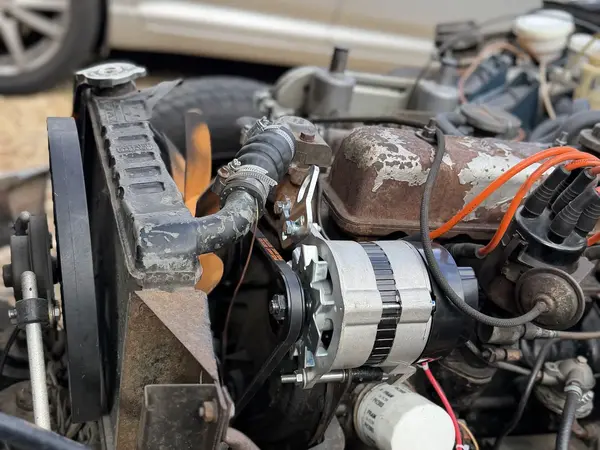 The GEU216 alternator fitted to the Spitfire Mk3 engine
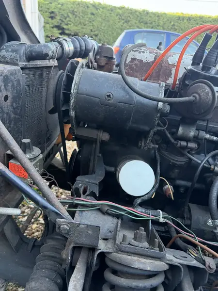 The Spitfire as it arrived: the original long black C40 dynamo on the left-hand side of the engine. MG Midgets and MGBs have their dynamo on the right-hand side of the engine.
Before you start: check your polarity
An alternator can only be fitted to a negative earth car (-VE). My Mk3 was already negative earth. If yours is still positive earth (+VE), the car must be converted to negative earth first.
For a Spitfire Mk3, what you'll need
| Part no. |
Description |
Used for |
| GEU216 |
Alternator, 16/17ACR 55 amp |
Supplied with fan, pulley and plug retaining clip |
| GEU250 |
Alternator plug kit |
Three-pin plug: two large output spades and one small warning light spade |
| BH605181 |
Bolt, 5/16 UNF x 2 1/4" |
Adjusting link into the cylinder head |
| BH605101 |
Bolt, 5/16 UNF x 1 1/4" |
Adjusting link to the alternator |
| 156464 |
Alternator adjusting link with lifting eye |
Top adjusting link |
| 2A7306 |
Tube, distance |
I used this as the spacer on the lower pivot bolt, with a GHF301 plain washer |
| GHF103 |
Screw, 5/16 UNF x 1" (x2) |
Bracket to engine |
| GHF201 |
Nut, plain, 5/16 UNF (x2) |
Mounting bolts |
| GHF332 |
Spring washer, 5/16 (x6) |
Under every nut and screw head |
| GHF301 |
Plain washer, 5/16 (x3) |
Mounting bolts and spacer |
| 147899 |
Lower alternator mounting bracket (Triumph part) |
As used on the Spitfire 1500. Not an MGOC stock item: from Triumph specialists or second-hand |
| Wiring |
About 1m heavy cable (65/0.30), brown or red |
Short link wire for B to D, plus the extra output cable to the solenoid |
| Wiring |
Terminals and connectors |
A crimped connector to join WL and F, a ring terminal, and a selection of Lucar male and female terminals and eyelets |
For MGB and Midget owners
MGBs and Midgets fitted with the Lucas RB340 control box (our GEU6605 fits both) use exactly the same wiring method below: link B to D, and join F and WL off the box. Wire colours can vary between cars, so always go by the letters stamped on the box, and check your car is negative earth first. The difference is the mounting: instead of the Spitfire bracket, use our ALT1 alternator conversion bracket kit, which is designed for MGB and Midget engines. Your bill of materials is:
- ALT1 alternator conversion bracket kit (MGB and Midget): the bracket, bolts, nuts and washers, plus a three-pin alternator plug with its terminals (two large 3/8" (9.5mm) output terminals and one small 1/4" (6.3mm) warning light terminal, the same as our GEU250 plug kit), so you don't need a separate plug kit
- GEU216 alternator, 16/17ACR 55 amp
- About 1m of heavy brown or red cable (65/0.30), a large insulated spade for the B to D link, a crimped connector for WL and F, and a ring terminal for the solenoid
- A fan belt to suit your engine with the alternator fitted
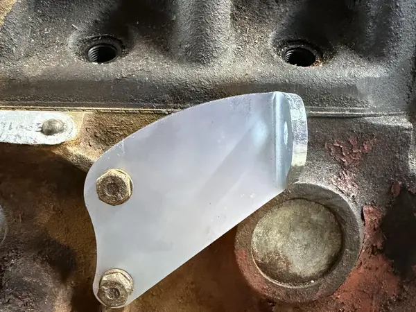 The ALT1 bracket fitted to an early MGB block. This is how it is arranged on 18G, 18GA and 18GB engines.
Note: when fitting the brackets, keep everything loose. Run each bolt in a good few turns, but don't tighten anything to the block or to the alternator yet. If you tighten the bracket up first, it can look as if the alternator won't line up with the crank pulley. Line the alternator pulley up with the crank and water pump pulleys first, then tighten everything carefully, keeping that alignment so the belt doesn't run askew. This is good practice on any conversion, whether MGB, Midget or Triumph.
It matters more on the MGB and Midget because the front of the alternator bolts to the water pump casting rather than to a lifting-eye bracket. Differences in the thickness of that casting change how far in or out the alternator needs to sit, which is why the ALT1 kit has a split bush at the back, so you can shunt the alternator forward or back to get the belt in line.
Step 1: remove the dynamo
- Disconnect the battery negative lead.
- Label the two dynamo wires: the thick brown/yellow (D) and the thinner brown/green (F).
- Slacken the adjusting link and pivot bolts, remove the fan belt, then lift the dynamo out.
- Remove the old dynamo brackets, including the rear strap bracket beside the distributor. They are not reused.
- Take the opportunity to clean the brackets and check the engine earth strap.
Step 2: fit the lower bracket
Bolt the 147899 bracket to the engine front plate with the GHF103 screws and GHF332 spring washers. It must sit completely flat.
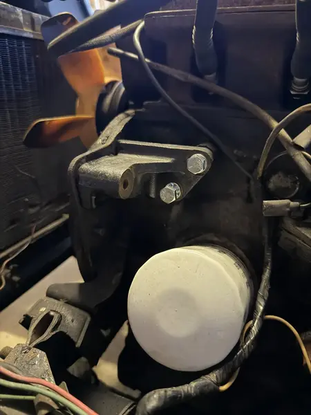 The lower alternator bracket bolted to the engine, ready for the alternator.
Step 3: hang the alternator
Offer the alternator up so its two lower lugs sit either side of the bracket. Slide the long pivot bolt through the rear lug, the spacer (our 2A7306 distance tube and a GHF301 washer), the bracket and the front lug, then fit a GHF301 plain washer, a GHF332 spring washer and a GHF201 nut. Leave it finger tight for now. We used plain nuts with spring washers throughout rather than nyloc nuts.
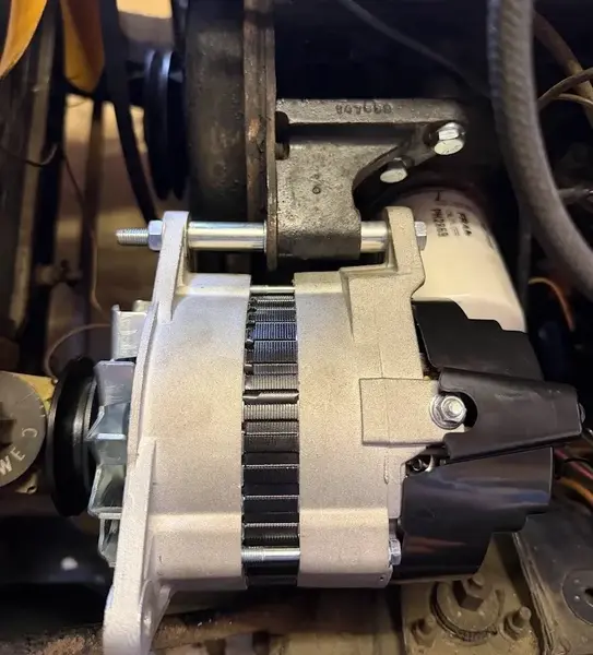 The GEU216 hung on the new bracket. The shiny tube on the pivot bolt is the 2A7306 distance tube we used as a spacer.
We tapped the spacer along at the rear of the alternator to line the front alternator pulley up with the crank and water pump pulleys. The alternator pulley must sit on the same line, otherwise the belt will wear quickly or jump off. On my car the gap was around 33mm.
Step 4: adjusting link and fan belt
Fit the 156464 adjusting link using the BH605181 2 1/4" bolt into the cylinder head and the BH605101 1 1/4" bolt to the alternator, with spring washers and nuts. Refit the fan belt, then set the tension. Keeping all bolts loose, we used a pry bar between the engine block and the alternator body (near the pivot) to lever the alternator out and hold the belt at the right tension while tightening the bolts: the top adjusting link bolts first, then the bottom pivot bolt. Tightening in that order stops the alternator creeping back and losing tension. Aim for about 1/4" of movement either side of the belt's centre line. Too tight will wear the bearings. We fitted a new belt, the same length as the original, which was still the right size with the alternator in place.
Step 5: wiring
The Mk3 was fitted with a Lucas RB340 control box, the same unit found on many dynamo-era MGBs and Midgets, and the conversion method is the same wherever an RB340 is fitted. With an ACR alternator the box no longer regulates anything. It simply becomes a junction box. Note that on my car the terminals ran E, D, WL, F, B from left to right, so always go by the letters stamped on the box, not the position.
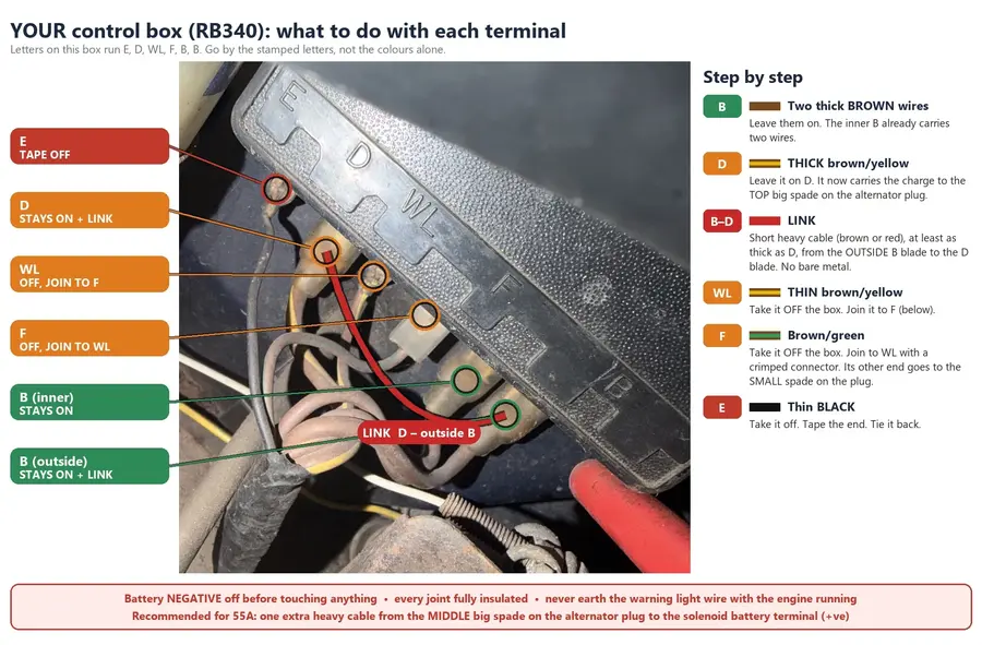 My RB340, with each terminal marked. The terminal letters run E, D, WL, F, B, B on this box.
| Terminal |
Wire |
What to do |
| B |
Brown (main battery feed) |
Leave connected. The link goes on the outside B terminal |
| D |
Thick brown/yellow |
Leave connected and link to the outside B with a short heavy cable. It now carries the alternator output |
| WL |
Thin brown/yellow |
Remove from the box and join to F |
| F |
Brown/green |
Remove from the box and join to WL. It now feeds the warning light |
| E |
Black (earth) |
Remove, insulate and tie back |
This is the standard, well-proven method for classic British dynamo-to-alternator conversions with RB340 regulators: link the B (+) terminal and the D terminal, and disconnect F and WL and link them together, but not through the control box.
A tip on the link: the RB340 has two B terminals, connected together inside the box. Use the outside B terminal for the link to D, because the inner B already carries two wires. On an MGB or Midget the two B terminals are linked inside the box in the same way, so the link can go on whichever B terminal is free.
At the alternator, the thick brown/yellow wire goes to the top large spade of the GEU250 plug, and the brown/green wire to the lowest, smallest spade. The middle large spade is for the extra output cable (below). Push the plug on and fit the retaining clip. On an MGB or Midget, the plug supplied in the ALT1 kit is wired in exactly the same way.
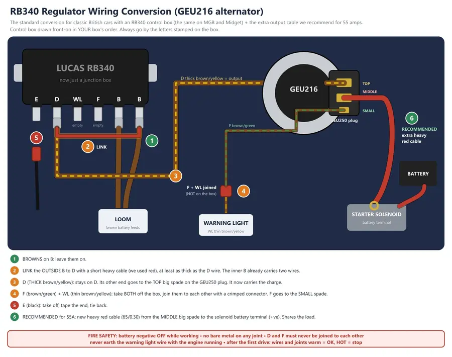 The complete wiring: B linked to D, F and WL connected together off the box, E taped off, plus the recommended extra output cable from the alternator's middle terminal to the solenoid battery supply (+ve).
Recommended: an extra output cable. The original brown/yellow wire was sized for a 22 amp dynamo. As Roger Parker explains in our Alternator Upgrades blog, a 55 amp alternator is best served by doubling up the output. Run one new heavy red cable (65/0.30) from the middle large spade of the plug to the battery terminal on the starter solenoid, with a properly crimped ring terminal. The two wires then share the load. After testing with a multimeter, route it along the existing harness and cable-tie it. The same goes for an MGB or Midget: take the extra cable to the battery terminal on the starter solenoid, where the main battery cable connects, rather than all the way back to the battery (on an MGB the battery sits behind the seats).
A note on colour: we used red cable for the link and the extra output cable. Electrically it makes no difference at all: what matters is the cable's size and the quality of the crimps, and red cable of the same size carries exactly the same current as brown.
The wiring in pictures
Here is how the wiring went together on my car, in the order we did it.
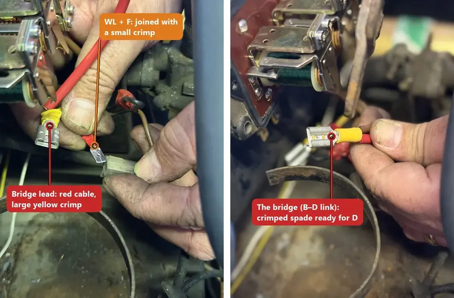 1. Crimping the connections: the red bridge lead (B to D link) with its large yellow spade, and WL and F joined with a small crimp.
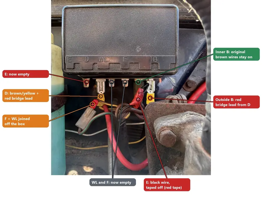 2. The finished control box, front on: the red bridge lead links D to the outside B, WL and F are off the box and joined together, and E is taped off.
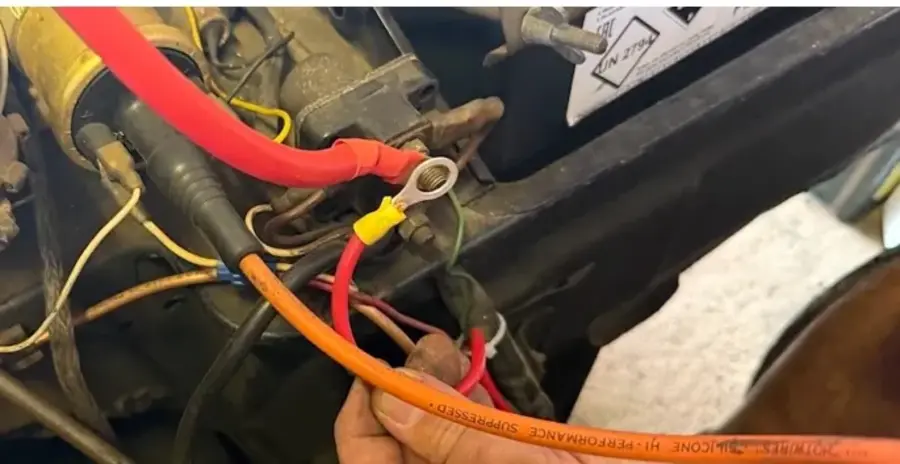 3. The new cable's ring terminal going onto the battery terminal of the starter solenoid, where the main battery cable connects.
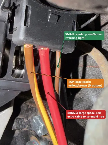 4. The GEU250 plug on the back of the alternator: yellow/brown on the top large spade, the red extra cable on the middle large spade, and green/brown on the small spade.
Step 6: testing
- Reconnect the battery.
- Test the voltage: this should read 12.5 volts +/-0.5V.
- Turn the ignition on: the red ignition warning light should come on.
- Start the engine: the ignition warning light should go out.
- With the engine running, test the voltage across the battery terminals with a voltmeter. At around 2,000 to 2,500rpm you should see 13.8 to 14.4 volts.
After the first drive, feel the output wires and joints. Warm is fine. Hot means stop and find the cause.
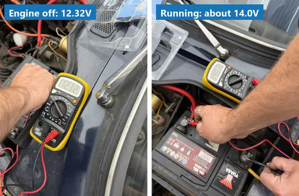 The proof: 12.32V with the engine off, around 14.0V with it running. The alternator is charging.
Wiring: the technical details
For those who like to understand what is going on behind the connections, here is the theory, drawn from our own technical blogs and product notes.
How the warning light switches the alternator on
An ACR alternator can't start charging on its own at low revs. When you switch the ignition on, a small current flows from the ignition switch, through the warning light bulb and into the alternator's small IND terminal. This energises the alternator so it can begin to charge. Once it is charging, its IND terminal rises to battery voltage, there is no longer a voltage difference across the bulb, and the light goes out. This is exactly why the old F and WL wires are joined: together they become the warning light feed. As our GEU216 product notes explain, a filament bulb acts as a resistor and passes that energising current, whereas an LED only passes current one way. With an LED fitted, the light stays on and the alternator won't charge until around 2,500rpm, when it self-energises.
- Keep a conventional filament bulb of around 2 watts in the ignition warning light, not an LED. This applies to the Spitfire, MGB and Midget alike.
- Never earth the warning light (IND) wire with the engine running. On most alternators this causes damage.
- Test the circuit safely with the engine stopped: ignition on, and the light should come on.
Why the control box is bypassed
A dynamo needs a control box to regulate its output and to stop the battery discharging back through it. The ACR alternator has its own regulator and diodes built in, so the RB340 simply stays where it is as a junction point. Every joint must be fully insulated and rated at least as heavily as the wires it joins: these are the car's main power feeds, and a short can cause a fire.
To put the demand in context, headlights, wipers and heater together can easily need 20 amps on a winter night, the whole output of a C40 dynamo. The 55 amp alternator covers that with plenty to spare.
Result?
With the extra electrical load from the amplifier and speakers, and everything else I was asking of the battery, the old dynamo simply couldn't keep up. Now the car has a charging system that can power it all, in any driving condition.
Related reading
See our full range of Classic MG Parts here. For further information contact our helpful sales advisors by phone on +44 (0)1954 230 928 or email at sales@mgocspares.co.uk.
Please Note: The information provided in this blog is intended as a general guide only. While we aim to ensure accuracy, classic vehicles can vary, and procedures may differ depending on model and condition. Always consult your vehicle’s official workshop manual before carrying out any work. If in doubt, seek the services of a qualified professional.
© 2026 MGOC Spares Ltd. All rights reserved.
This blog and its contents are the intellectual property of MGOC Spares Ltd and may not be copied, reproduced, or republished without prior written permission.
For author enquiries, corrections, or reproduction requests, please contact: blog@mgocspares.co.uk
Who are MGOC Spares?
At MGOC Spares, we provide dedicated parts and accessories for classic MG vehicles, including the MGB, Midget, MGC and many more, plus spares for other British classics.
With thousands of products in stock, we are your one-stop shop for all your classic car needs. Our wealth of expertise means that you can trust us to find the right part for your classic car, whatever it may be.
Need support finding the right parts? Contact us today, we're happy to help!