Carburettor Maintenance
Part three in a four part series covering many of the common problems and some of the solutions often found within the MGBs fuel system, and many of which can also apply to most other MGs running SU carbs.
The fuel pipe enters the rear of the engine bay by the heater and from there connects to fuel hoses in one of two common formats. Early cars with HS4 carbs sees the hose from the underfloor pipe connect to a three-way metal Tee piece located between the rear carb and the engine, and then from one outlet on the tee piece, a short hose feeds the rear carb float chamber. From the remaining outlet on the Tee piece is a longer hose that runs forward and to the float chamber of the front carb.
 The fuel pipe run seen here on chrome bumper cars with HS carbs runs from by the heater box across to a Tee piece to feed the rear carbs' float chamber, and then forward to feed the front carb.
HS4 carbs were replaced by HIF4 carbs on export MGBs from the start of 1972 model year (production line from August 1971); ‘Home’ market cars didn’t catch up with the introduction into production until November 1973, although in the intervening decades carbs have occasionally been swapped by owners. The pipe runs on cars equipped with HIF carbs saw two slight pipe/hose run variations, although the actual route for both was across to the left side inner wing and forward towards the radiator before adopting a U turn to fit to connect into the fuel intake port pipe on the side of the front HIF carb facing the radiator. With the fuel feed pipe only feeding into the front HIF carb, getting fuel into the rear carb now needed an open port in that front carb that allowed fuel to flow out the opposite side of this carb via a second pipe connecting to a very short hose that feeds fuel into the rear carbs fuel inlet. MGOC Spares stock a range of tailored braided kits for HS4 (1/4”) & HIF4 (5/16”) carburettor MGs, that is E10 compliant.
 This view of twin HS4 carbs with the bulky air filters removed shows the fuel feed hose run more clearly.
 One quite common owner error is to fit the hoses to the front HIF carb incorrectly and cause flooding. The fuel feed hose connects to the green arrow position and the carb overflow pipe connects to the red arrow position.
The introduction of the HIF4 carbs also saw the first standard use of such a simple but most important addition, a simple in-line fuel filter, mounted in the fuel line as it runs to the left inner wing and down towards the front carb, although the actual filter position varied between chrome bumper cars with HIF carbs and the filter closer to the heater on rubber bumper cars. A filter wasn’t seen in standard form on the earlier HS4 cars, which today is something that really should be added if not already done so, especially as ethanol in fuel tends to disturb previously settled tank sediment. Note that fitting to a chrome bumper car will demand minor additional hose changes depending on what filter set up is chosen, however the overall cost can be very low with the same filter fitted to the HIF MGBs (See FUEL FILTER MGB+V8 (PLASTIC) but the benefits can be significant.
 Whilst a standard use of a fuel filter on MGBs didn’t arrive until 1973 with HIF carbs, it has always been a sound idea to fit one, and more so in recent times. Here, a beautifully rebuilt 1966 MGB shows a neat installation of a filter.
 By contrast chrome and rubber bumper MGBs that use the HIF carbs see their fuel pipe run by the heater across to the left inner wing, then passing through a filter to feed the front carb. Feed to the rear carb being through a short hose between the carbs.
 With air filters removed here the short interconnection hose between front and rear HIF carbs can be seen.
Firstly you will note that in normal use the filter will never be completely full, something over half full to around three quarters. Make a mental note of this as it can become a very good indicator of developing fuel pump issues because levels less than half full generally indicate a fuel supply problem. Another benefit is that being transparent you get an immediate visual clue if there is any debris movement as it will collect and be seen in the filter, and of course not cause any carb blockages. If there is any sign of debris then do replace the filter and if the new filter becomes dirty then consider removing and cleaning out the fuel tank. Note; service replacement of the fuel filter was every 12,000 miles, which today is often many years of motoring so for these cars change at no later than five year intervals, or sooner if desired.
 This typical filter used on MGBs shows the important correct direction of flow for the fuel through the filter. Note some filters have the arrow moulded into the filter body and it’s not easy to see.
At this point whilst looking at fuel filters it is worth considering an additional filter mounted in the pre-pump position, an addition that has gained momentum in recent years, although there is no technical need for one. However, fitting one will filter the fuel before it can get in the fuel pump and help reduce potential of any in tank muck able to pass the tanks filter screen causing issue with the fuel pump. Note; this pre-pump configuration mimics the MG RV8 set up that specifically had a pre-pump filter of the same type as fitted to the standard MGB because the RV8 pick-up pipe in the tank did NOT have a filter screen. It was open ended as a filter screen created too much flow restriction for the Bosch high pressure/volume fuel injection pump, which delivers fuel at well over ten times the pressure of a carburettor pump, and with much increased volume.
 This image here shows an inline filter fitted before the pump, as original on the MG RV8. Although not standard, fitting an inline filter before the pump on an MGB can safeguard fuel pump failure from debris in the tank; ultimately, in such circumstances, the tank should be replaced.
After that segway on fitting an extra filter we move back into the engine bay and follow the fuel as it passes through the float valves, also known as metering needles of the MGBs twin carbs. The float valves are very simple devices where a pin with a conical end slides inside the float valve body and its maximum upward movement sees this conical end engage in a hole in the main valve body that shuts off further fuel supply. The other end of the pin is in contact with the float arm with the pin able to move up or down in unison with the float's movement. When the fuel level in the float chamber is low the float will be low and the float pin will drop and no longer be in contact with its seat. This allows fuel to flow into and fill the float chamber that causes the float to rise and once again, the conical end of the pin reaches and sits on its seat and stops further flow. This is constantly repeating to maintain the fuel level in the float chamber whilst the engine is running.
The conical seat of the pin was for many years made from brass, as is the main valve part of the float valve, but over time it does wear and somewhat faster with modern fuel. This results in a visible ring mark running around the conical part of the pin about halfway up and often if you run a fingernail across the ring you will feel it catch. This is bad for accurate fuel control and is the signal to replace the whole float valve IN BOTH carbs. Whilst the same valve is applicable to both HS and HIF carbs you can find slight variations, one way to improve the sealing of the valve was to use Viton tipped conical ends and these have been around for decades, although SU themselves have now standardised this as it has better resistance to modern fuel. SeeStayUp Float Kit HS.
 Comparison of typical new, (left) and used float valves and seats. Note the marking on the conical end of the used valve at the bottom of the right image that demanded its renewal.
Floats on HS carbs have always been hollow plastic mouldings that then had a metal arm to connect it to the pivot point on the float chamber lid. Originally this was riveted to the float to allow slight bending of the arm to set the fuel height in the float chamber, along with occasional use of thin washers between the float valve body and the float chamber lid. Issues of fuel leaking past the rivets into the float saw the float design change long ago into a full plastic moulded float integrating the arm, so no rivets to leak but this also removed any effective float level adjustment.
 This is a typical fully moulded plastic HS float and chamber gasket, the moulded end not allowing for any adjustment of fuel height.
Floats on the HIF4 carbs are considerably bigger and also handed, although still full plastic mouldings but with fuel height adjustment capability. Being bigger, they are able to impart more pressure onto the float pin and why the HIF carbs can cope with higher peak fuel pressures than the HS floats. Of course, both types must remain sealed, so any fuel that is able to leak inside a standard float means the float needs immediate replacement. This is usually evident from carburettors which pour fuel out of the carburettor overflow hoses.
 This is the larger HIF float that has failed as it allowed fuel to leak in and render it useless.
This isn’t the end of float discussion though as the arrival of higher concentration ethanol has been shown to degrade some floats and cause leaks. Interestingly in the 1980’s a requirement to eliminate any risk of carb float failure in military vehicles saw SU develop the closed cell float (i.e. not hollow) made from materials that would not react to ethanol or other nasties to keep military vehicle engines running in combat environments. The SU Carb Company has used this material in the current range of floats that is supplied to distributors such as MGOC Spares and shown under their ‘StayUp’ title. (StayUp Float HIF Rear and StayUp Float HIF Front)
 AUE896 - HIF 'StayUp' Float Front
For new floats, the StayUp type have replaced the original vacuum moulded plastic floats for HIF and HS carburettors. With the ‘StayUp Float’ option for the HS4 floats it is very pleasing to note that they now once again provide easy adjustability of the arm to correctly set float heights. Whilst more expensive, and of course you need two for an MGB or any other twin carb MG, they should pay for themselves with longer and more accurate operation so reducing fuel wastage and emissions.
 WZX1300 - HS4 StayUp Float
Once fuel has been allowed into the float chamber by the float valve it sits there until needed by the engine. As the engine fuel demands are least when the engine is at idle or on a very light throttle in slow moving traffic is when we often see engine and exhaust heat able to enter the fuel which can cause running problems. There is no single cure for these running problems, other than to say any changes that can insulate the fuel lines and carbs from this ever present heat can delay the onset of fuel evaporation.
However, it is when the engine is switched off that the full float chambers can sit with this fuel for variable periods of time before the ignition is switched on again. Initially, after a fully warmed engine stops heat will quickly be conducted back up through the inlet manifold and into the carbs, as well as rising up from the exhaust and this will heat the fuel in the float chambers to higher temps and create accelerated evaporation of the volatile elements of that fuel. Once all those volatile elements have gone, what will be left will be gummy deposits in the bottom of the float chamber and the fuel paths into the main jet. In short periods of time until the ignition is next switched on those deposits will usually be dissolved by fresh fuel, but, over longer periods such as over winter storage, then those gummy deposits tend to harden into a varnish like substance that will not readily dissolve in fresh fuel and will reduce internal fuel flow, or even block it.
Carburettor Spring Clean
In my decades of providing technical advice for MG owners it was common in spring to expect a steady flow of owners contacting and asking why their MG was running so sweetly in the previous autumn, but having just got the car out from its winter slumber it now runs so badly with difficult starting, lumpy idle and flat spots when trying to drive, often needing to have the choke out much more to keep it going.
I think the reader will have already clocked where I am going with this as the reason was almost always related to the fuel residues hardening into a varnish and restricting fuel flow. Whilst occasionally, they could stick the float valves shut, they do more commonly leave a hardened deposit over the metering aspects of the valves that can reduce the valves sealing efficiency. However, it is in the float chambers where there are more of these deposits that often restrict the pathway to the main jet and where restricted flow has more impact on the engine running.
The design of the HS float chamber and pipe from it to the main jet is more vulnerable to this than the later HIF carbs simply because the fuel runs right from the bottom of the float chamber into the nylon tube (covered with a steel braiding) that connects to the bottom of the main jet. This is where most fuel deposits collect and restrict it and is the cause of many spring time poor running issues when it was fine the previous autumn. Usually at this point owners dive under the bonnet and start fiddling with carb mixture and idle settings – DON’T, at least not unless you have tried the following clean.
I have for many years advocated carburettor MGs are treated to a ‘Carburettor Spring Clean’ that can be achieved really quite easily with little effort, little dismantling and little expense. The expense part is to simply, but specifically buy an aerosol can of Carburettor Cleaner spray, or choke cleaner (different name), but make sure that you have a plastic straw to be able to accurately direct the spray.
 BCC500 - Aerosol Carburettor Cleaner
Ideally, before touching the car do not switch on the ignition so you do not allow the fuel pump to fill the carb float chambers as it allows the cleaning spray to be more concentrated and its effect not diluted by fuel. Dismantling involves unscrewing and removing the damper on top of the carbs dashpots, then the three screws holding the dashpots to the carb body and carefully lifting it off and placing to one side. Then lift out the dashpot spring followed by the piston assembly and place carefully to one side, being very careful not to allow the needle to be placed under any pressure as it is easily bent.
You now move your attention to the fuel feed hose(s) feeding fuel to the carbs which are very simple to see on HS carbs so undo the hose clips and slide them off, but do wrap a cloth around the first one as there may still be some residual fuel pressure that will want to spray out. The HIF carbs are more complex as there is only one accessible fuel feed hose on the front facing side of the front carb that is often confused with the closely located, (slightly higher and to the left when looking from the front of the car) float chamber overflow hose. (See image of HIF feed hose above.) Next, the rear carb gets its fuel flow from a cross over passage inside the front carb allowing fuel to flow out of that carb into a short interconnection hose between front and rear carb. (This can be seen below the choke linkage on the image above)
For both types of carb the next action is to place the plastic straw of the side of the can of carb cleaner into the spray nozzle, then place the other end of the straw just inside the pipe that the fuel hoses have just been removed from and give a two to three second spray that will soak the float valves. With the HIF carbs you can now insert the straw a little further inside that pipe and repeat the spray as that will allow spray to pass through the interconnection hose between front and rear carb to soak around the rear carb's float valve. Allow a couple of minutes to pass and then repeat for both carbs.
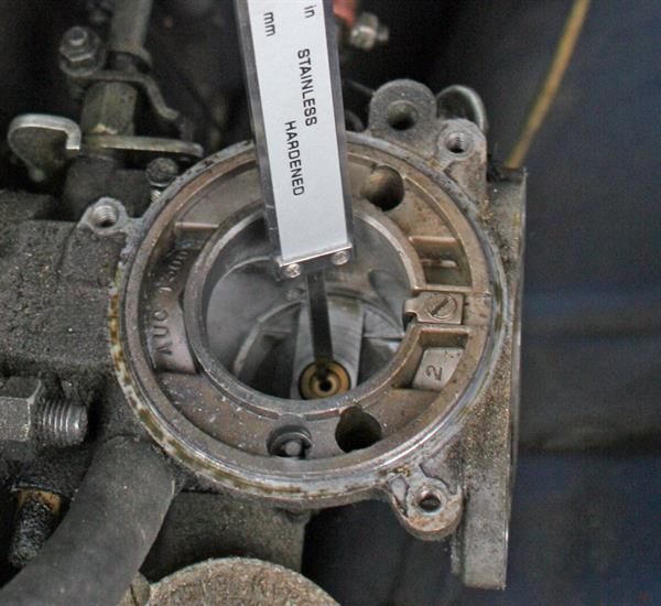
The second action is to look down the now open top of each carb where you can see the small hole in the brass main jet (see image) that you again insert the straw just into the top and give each carbs main jet a two to three second spray with a couple of minutes pause before repeating. Carburettor cleaning spray will instantly dissolve dried fuel deposits and give a strong blast into the float chambers taking anything else that may be in this area with it, whilst preserving the integrity of the seals.
You can see how effective this spray is on dried deposits as you now have the opportunity to spray the removed pistons, inside the dashpots and the accessible inner areas of the carb bodies. Once reassembled, don’t forget to add fresh oil into the dashpots. Note that initial starting may be upset by the volume of carb cleaner still present in the float chambers, so a little throttle to raise revs for the first few seconds after starting to clear these may be needed. (Note here that you should not use any abrasive on the outer ribbed rings of the main piston or inside the dashpot as removing metal here compromises the seal between these two items when the carb is reassembled.)
Prevention is often better than the cure, I recommend using high RON fuels (super unleaded) with fuel additives such as Valvemaster Plus (which includes fuel stabiliser) to optimise the quality of fuel into the carbs and reduce volatility. When laying up, draining off the fuel from the tank, disconnecting the live power feed to the fuel pump and running the engine at idle for a couple of minutes until the engine cuts out will make recommissioning easier in the springtime.
In part 4, we'll be looking more into carburettor wear.
Please Note: The information provided in this blog is intended as a general guide only. While we aim to ensure accuracy, classic vehicles can vary, and procedures may differ depending on model and condition. Always consult your vehicle’s official workshop manual before carrying out any work. If in doubt, seek the services of a qualified professional.
© 2025 MGOC Spares Ltd. All rights reserved.
This blog and its contents are the intellectual property of MGOC Spares Ltd and may not be copied, reproduced, or republished without prior written permission.
For author enquiries, corrections, or reproduction requests, please contact: blog@mgocspares.co.uk
Who are MGOC Spares?
At MGOC Spares, we provide dedicated parts and accessories for classic MG vehicles, including the MGB, Midget, MGC and many more.
With thousands of products in stock, we are your one-stop shop for all your classic car needs. Our wealth of expertise means that you can trust us to find the right part for your classic MG vehicle – whatever it may be.
Need support finding the right parts for your MG? Contact us today, we're happy to help!